KEYBOARD INTERFACING WITH 8051 MICROCONTROLLER
5.1 Introduction
The predominant interface between humans and computers is the keyboard. Keyboard range in complexity from the “up-down” buttons used for elevators to the personal computer multimedia keyboard layout, with the addition of function keys and numeric keypads. One of first requirement was to interface keyboard with microcontroller and with the main processor in personal computers. Industrial and commercial applications fall somewhere in between these extremes, using layouts that might feature from six to twenty keys. One of the most basic requirements in configuring a keypad is to accommodate need of human user. Human beings are irritable. They have little tolerance for machine failure. You have seen the behavior of people at the elevator. Even if the “up” light is lit when we arrive, we will push it again to let the machine know that “I’m here too.” Thus the hardware designer has to select keys that will survive in the intended environment. The programmer must write the code that will anticipate and defeat deliberate attempts by human to confuse program. The software must be such that the keyboard application must guard against following Human Factors:
1. More than one key pressed.
2. Key pressed and held.
3. Rapid key press and release.
5.2 Keyboard Configurations
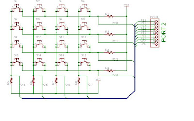
Keypads are often used as a primary input device for embedded microcontrollers. At the lowest level keypads are arranged as a matrix of rows and columns which are for by using number of switches as shown in Fig 5.1 and Fig 5.2 shows how it looks on real hardware. The CPU accesses both rows and columns through ports; therefore, with one bit ports a 4×4 matrix keys can be connected to a microcontroller. When a key is pressed the row makes a contact with column. Otherwise there is no connection between rows and columns. Microcontroller itself makes a continuous check of all rows and columns with the help of program stored in its ROM to see whether a key is pressed or not, It takes care of both hardware and software. In order for the microcontroller to scan the keypad, it outputs a nibble to force one (only one) of the rows and then reads the columns. If any keys in that column have been pressed. The rows are pulled up by the internal weak pull-ups in the 8051 ports. Consequently, as long as no buttons are pressed, the microcontroller sees logic high on each of the pins attached to the keypad rows. The nibble driven onto the columns always contains only a single 0. The only way the microcontroller can find a 0 on any row pin is for the keypad button to be pressed that connects the column set to 0 to a row. The controller knows which column is at a 0-level and which row reads 0, allowing it to determine which key is pressed. For the keypad, the pins from left to right are: R1, R2, R3, R4, C1, C2, C3, and C4. Next section shows you how to detect a key press using 89C51.
5.3 SCANNING AND IDENTIFYING KEY PRESS
Here we have used 4×4 matrix keyboard. Its interfacing to 89C51 is as shown in
Figure. Rows are connected to the output port and columns are connected to input port. If no key is pressed then the status of all columns will be high at Vcc. If all rows are grounded and a key is press, then the status of one of the column will goes low since the key provides path to ground. Using the above procedure Microcontroller scans continuously and detects a key press. To detect key press, the microcontroller grounds all rows by providing 0 to the output latch, then it reads the columns, If date read is p0.4-p0.7=1111, no key is pressed and process continues until a key press is detected. When a key press occurs, one of the columns will go zero. For example, if p0.4-p0.7=1101 this means that key of column-3 that is connected to p0.6 is pressed. After the key press is detected than microcontroller goes for identifying a key. Starting with the top rows microcontroller continuously ground each of the row and check corresponding column. If the column status is all high then no key is press and process is moved to next row.

5.4 HARDWARE CRITERIA
Figure shows interfacing of 89c51 with 4 x 4 matrix keyboard. Here rows are connected from p0.0-p0.3. While columns are connected from p0.4-p0.7.
5.4.1 TO DETECT MATRIX KEYBOARD USING 4 LEDs.
Display Keypad Data to LED:
In this lesson we are like to design, how to scan keypad 4 x 4, and then display it to LED. In this hardware 4*4 keyboard is connected to eight port pins. And 4 LEDS are connected to four other port pins. All cathodes of LEDS are shorted and grounded while anode of each LED is connected to port pin via pull up resistor. Which key is pressed on key board (0 to f keys) hex value of this key digit is displayed on four LEDS. If 0 key is pressed all four LEDS are off. If 1 key digit pressed 0001 pattern will be displayed on LEDS.

Comments